BookmarkBookmark
テキスト表示モード

Thermal Management Solutions
Thermal Management Solutions
Product Lines
Product Lines
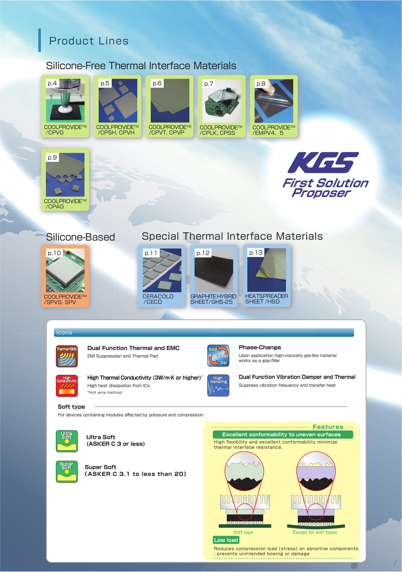
Silicone-Free Thermal Interface Materials als p.4 p.5 p.6 p.7 p.8 COOLPROVIDE TM
/CPVG COOLPROVIDE TM /CPSH, CPVH COOLPROVIDEOVIDE TM
/CPVT, CPVP COOLPROVIDE TM
/CPLK, CPSS COOLPROVIDE TM
/EMPV4,5 p.9 COOLPROVIDE TM
/CPAG
First Solution Proposer
Silicone-Based Special Thermal Interface Materials p.10 p.11 p.12 p.13 COOLPROVIDE TM
/SPVS, SPV
CERACOLD /CECD
GRAPHITE HYBRID SHEET/GHS-25
HEATSPREADER SHEET /HSD
Icons
Thermal+EMC
Dual Function Thermal and EMC
EMI Suppression and Thermal Pad
Solid Phase Change
Gel
Phase-Change
Upon application high-viscosity gel-like material works as a gap-filler
High Conductivity
High Thermal Conductivity (3W/m·K or higher) *
High heat dissipation from ICs
High damping
Dual Function Vibration Damper and Thermal
Suppress vibration frequency and transfer heat
*Hot wire method
Soft type
For devices containing modules affected by pressure and compression
Ultra Soft
Ultra Soft (ASKER C 3 or less)
Features Excellent conformability to uneven surfaces
High flexibility and excellent conformability minimize thermal interface resistance.
Super Soft
Super Soft (ASKER C 3.1 to less than 20)
Soft type Low load
Except for soft types
Reduces compression load (stress) on sensitive components ; prevents unintended bowing or damage
Product Spotlight
Product Spotlight
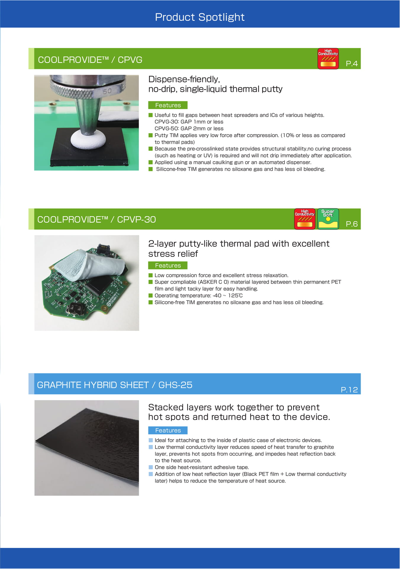
COOLPROVIDE™ / CPVG
High Conductivity
P.4
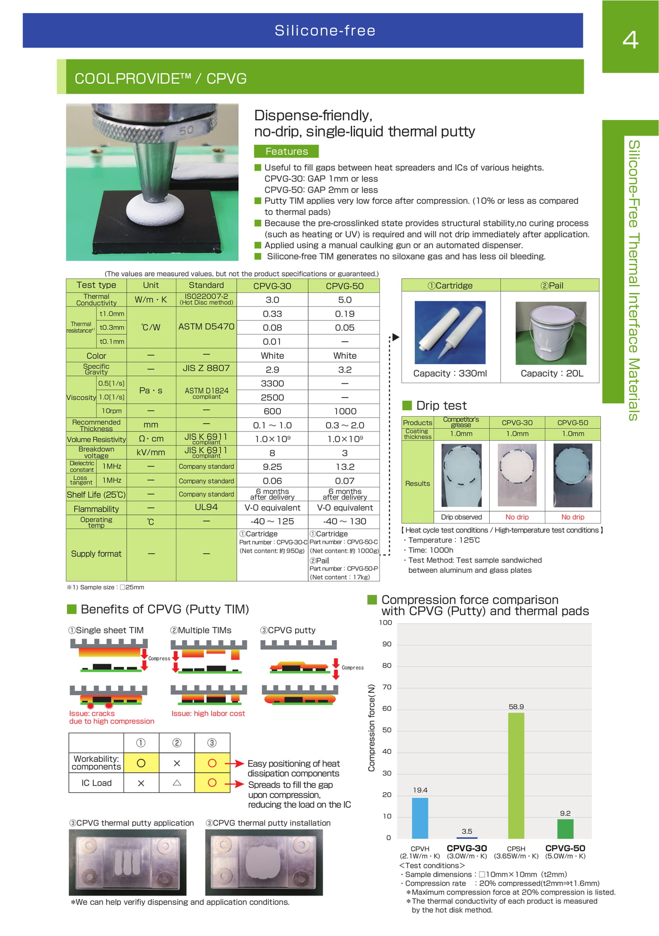
Dispense-friendly, no-drip, single-liquid thermal putty
Features ■ Useful to fill gaps between heat spreaders and ICs of various heights. CPVG-30:GAP 1mm or less CPVG-50:GAP 2mm or less ■ Putty TIM applies very low force after compression. (10% or less as compared to thermal pads) ■ Because the pre-crosslinked state provides structural stability,no curing process (such as heating or UV) is required and will not drip immediately after application. ■ Applied using a manual caulking gun or an automated dispenser. ■ Silicone-free TIM generates no siloxane gas and has less oil bleeding.
COOLPROVIDE™ / CPVP-30
High Conductivity
Super Soft
P.6
2-layer putty-like thermal pad with excellent stress relief
■■■■ Features
Low compression force and excellent stress relaxation. Super compliable (ASKER C 0) material layered between thin permanent PET film and light tacky layer for easy handling. Operating temperature: -40 ~ 125℃ Silicone-free TIM generates no siloxane gas and has less oil bleeding.
GRAPHITE HYBRID SHEET / GHS-25
P.12 P.8
Stacked layers work together to prevent hot spots and returned heat to the device.
■■■■ Features
Ideal for attaching to the inside of plastic case of electronic devices. Low thermal conductivity layer reduces speed of heat transfer to graphite layer, prevents hot spots from occurring, and impedes heat reflection back to the heat source. One side heat-resistant adhesive tape. Addition of low heat reflection layer (Black PET film + Low thermal conductivity later) helps to reduce the temperature of heat source.
Safety Guidelines
Safety Guidelines
Please review prior to using our products.
1. The contents or products described in this catalog may change without notice due to product improvements and specification updates.
2. All statements, specifications, properties, technical . information, and recommendations herein are based on tests; however, the accuracy and completeness of the values are not guaranteed.
3. Before exporting any product featured in this catalog, ensure compliance with the "Foreign Exchange and Foreign Trade Law." If cargo falls under this regulation, an appropriate export license is necessary. Additionally, be aware that certain countries and regions have restrictions on the sale of these products.
4. KGS assumes no responsibility for any issues related to our intellectual property rights or third-party rights that arise after the use of any product listed in this catalog. Furthermore, KGS does not authorize the licensing of these rights.
5. The content of this catalog applies solely to products purchased directly from us or through authorized agencies. If no information regarding the applicable conditions is provided, or if the products were purchased from a third party, the conditions outlined in the catalog do not apply.
6. Products in this catalog may not be available for sale depending on country or region.
7. Products listed in this catalog are designed and tested for general-purpose applications commonly found in various electronic devices and equipment, such as AV systems, office equipment, computer peripherals, communication devices, home appliances, industrial robots, entertainment systems, personal-use devices, measurement/test units, and similar applications. They are intended for use under normal operating conditions in these general electronic devices and equipment.
This catalog does not guarantee the product's performance or quality, particularly if the product is intended for use in high-safety and high-reliability or other very unique applications, or in situations where device failure, malfunction, or misuse could pose risks or harm to human life and health, cause property damage, or have significant social impact. Please consult us before using our products in these cases, especially if your requirements exceed the product's normal performance range and conditions specified in the catalog, or if you have specific application requirements.
① aerospace equipment, ② transportation equipment (automobiles, trains, ships, and similar vehicles), ③ nuclear power-related equipment, ④ medical equipment, ⑤ military equipment, ⑥ underwater/submarine equipment, ⑦ power generation control equipment, ⑧ public information processing equipment, ⑨ transportation control equipment, ⑩ electric heating equipment, combustion equipment, ⑪ disaster prevention, crime prevention equipment, ⑫ various safety devices, ⑬ other usage deemed to be unique applications.
While designing the equipment to use the product in this catalog, please secure a protection or a backup in accordance with the intended use of the device.
8. While we have implemented comprehensive measures to enhance the safety, quality, and reliability of our product, improper use may potentially result in personal injuries, fire hazards, or societal losses. Contact us for guidance on the correct use of our products.
Unauthorized reproduction or duplication of the contents of this catalog is strictly prohibited.
[Handling Procedures]
●During installation, avoid contact with the heating element to prevent any burns risks. ●Ensure the surface is free of dirt, dust, oil, or moisture before installing. ●Keep protective release liner in place until use to prevent contamination from debris and dust. ●Product thickness indicated in the catalog does not include the protective release liner. ●Store products at room temperature in a low humidity environment and avoid direct sunlight or UV rays. ●Phase-change gels must be stored below 35℃ (Recommended temperature is 25℃). ●Due to the inherent tackiness of our products, removal after heating or compressing may be challenging.
Applications
Applications
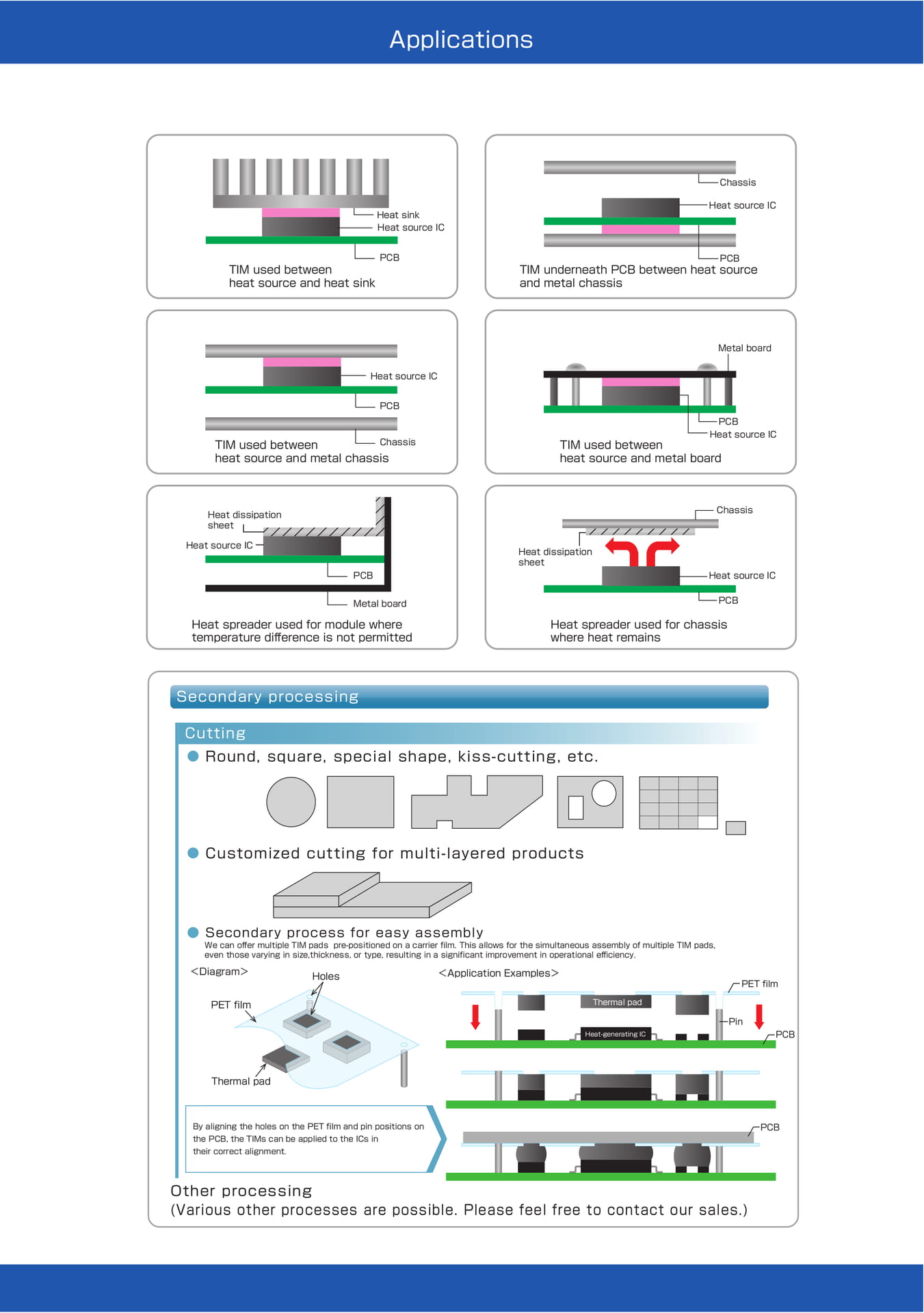
Chassis
PCB
基板 TIM used between heat source and heat sink
Heat sink ヒートシンク Heat source IC 発熱 IC
Heat source IC
PCB TIM underneath PCB between heat source
and metal chassis
Metal board
Heat source IC
PCB
TIM used between
Chassis heat source and metal chassis
PCB
Heat source IC
TIM used between heat source and metal board
Heat dissipation sheet
筐体 Chassis
Heat source IC 熱拡散シート
PCB
Heat dissipation sheet
Heat 発熱 ICsource IC
Metal board
PCB 基板
Heat spreader used for module where temperature difference is not permitted
Heat spreader used for chassis where heat remains
Secondary processing
Cutting ● Round, square, special shape, kiss-cutting, etc. ● Customized cutting for multi-layered products ● Secondary process for easy assembly
We can offer multiple TIM pads pre-positioned on a carrier film. This allows for the simultaneous assembly of multiple TIM pads, even those varying in size,thickness, or type, resulting in a significant improvement in operational efficiency.
<Diagram> Holes
<Application Examples> PET film
PET film
Thermal pad
Heat-generating IC
Pin PCB
Thermal pad
By aligning the holes on the PET film and pin positions on the PCB, the TIMs can be applied to the ICs in their correct alignment.
PCB
Other processing (Various other processes are possible. Please feel free to contact our sales.)
Silicone-Free Materials
1
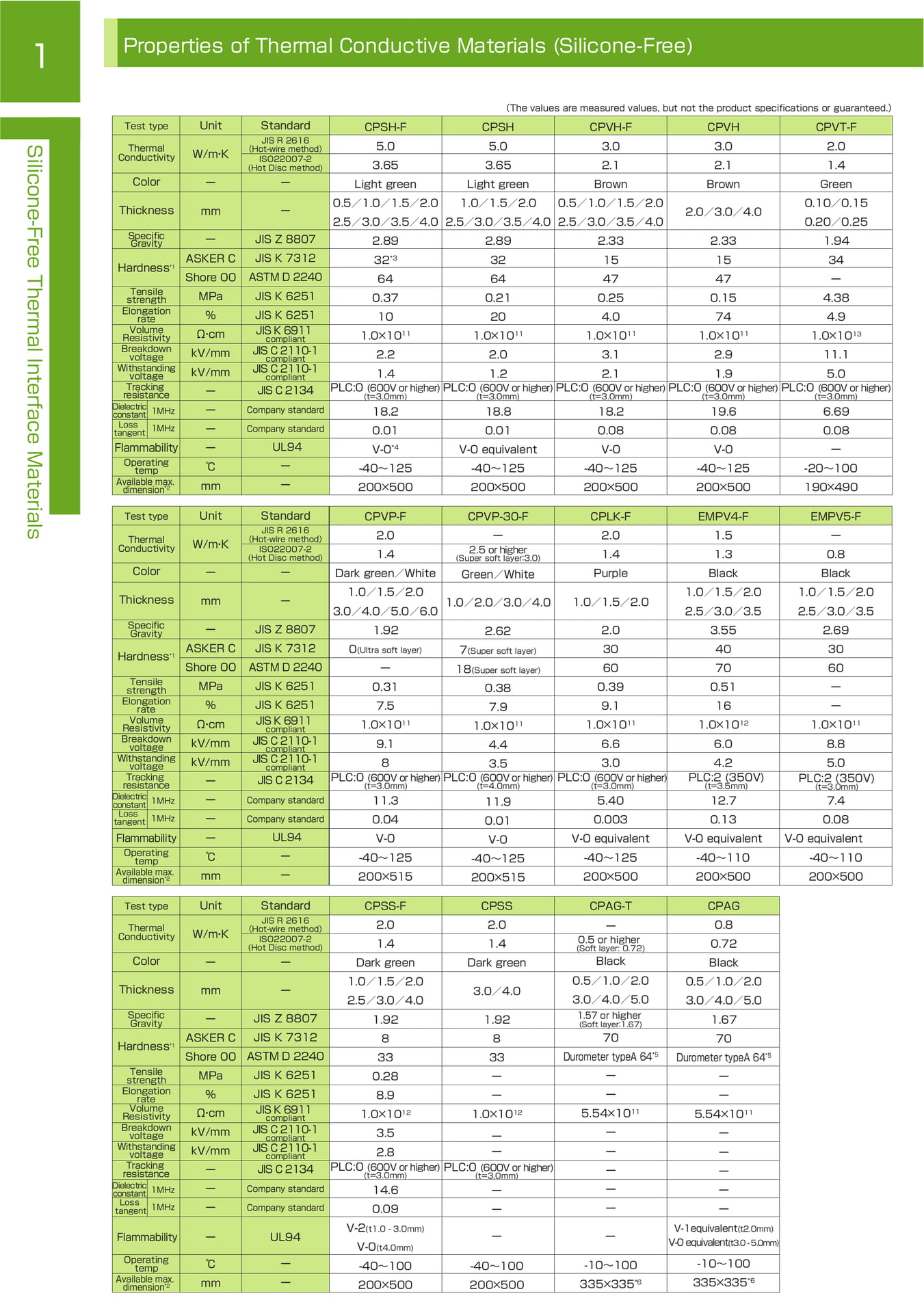
Properties of Thermal Conductive Materials (Silicone-Free)
Silicone-Free Thermal Interface Materials
Test type
Thermal Conductivity
Color
Thickness
Specific Gravity Hardness *1
Tensile strength
Elongation rate
Volume Resistivity
Breakdown voltage
Withstanding voltage
Tracking resistance
Dielectric constant 1MHz Loss tangent 1MHz
Flammability Operating temp
Available max. dimension *2
Test type
Thermal Conductivity
Color
Thickness
Specific Gravity Hardness *1
Tensile strength
Elongation rate
Volume Resistivity
Breakdown voltage
Withstanding voltage
Tracking resistance
Dielectric constant 1MHz Loss tangent 1MHz
Flammability Operating temp
Available max. dimension *2
Unit
W/m ・ K
ー
mm
ー ASKER C Shore 00 MPa %Ω・ cm kV/mm kV/mm ーーーー℃mm
Unit
Standard CPSH-F
JIS R 2616 (Hot-wire method) 5.0
ISO22007-2 (Hot Disc method) 3.65
ー Light green
0.5/1.0/1.5/2.0 ー
2.5/3.0/3.5/4.0
JIS Z 8807 2.89
JIS K 7312 32 *3
ASTM D 2240 64
JIS K 6251 0.37
JIS K 6251 10
JIS K 6911 compliant
JIS C 2110-1 compliant JIS C 2110-1 compliant
JIS C 2134
Company standard Company standard UL94 ーー
18.2 0.01 V-0 *4 -40~125 200×500
CPVP-F
W/m・ K
JIS R 2616
(Hot-wire method)
ISO22007-2
(Hot Disc method)
2.0
1.4
ー
ー Dark green/White
1.0/1.5/2.0 mm
ー
3.0/4.0/5.0/6.0
ー JIS Z 8807
1.92
ASKER C JIS K 7312 0(Ultra soft layer)
Shore 00 ASTM D 2240
ー
MPa JIS K 6251
0.31
% JIS K 6251
7.5
Ω・ cm kV/mm kV/mm ーーーー℃mm
Standard
JIS K 6911 compliant
JIS C 2110-1 compliant JIS C 2110-1 compliant
JIS C 2134
Company standard Company standard UL94 ーー 1.0×10 11 2.2
1.4 PLC:0 (600V or higher) (t=3.0mm) 1.0×10 11 9.1
8 PLC:0 (600V or higher) (t=3.0mm)
11.3
0.04 V-0 -40~125 200×515
(The values are measured values, but not the product specifications or guaranteed.)
CPSH
5.0
3.65
Light green
1.0/1.5/2.0
2.5/3.0/3.5/4.0
2.89
32
64
0.21
20 1.0×10 11
2.0
1.2
CPVH-F
3.0
2.1
Brown
0.5/1.0/1.5/2.0
2.5/3.0/3.5/4.0
2.33
15
47
0.25
4.0 1.0×10 11
3.1
2.1
CPVH
3.0
2.1
Brown
2.0/3.0/4.0
2.33
15
47
0.15
74 1.0×10 11
2.9
1.9
CPVT-F 2.0 1.4 Green 0.10/0.15 0.20/0.25 1.94 34 ー 4.38 4.9 1.0×10 13 11.1 5.0 PLC:0 (600V or higher) PLC:0 (600V or higher) PLC:0 (600V or higher) PLC:0 (600V or higher)
(t=3.0mm)
(t=3.0mm)
(t=3.0mm)
(t=3.0mm)
18.8 0.01 V-0 equivalent -40~125 200×500
CPVP-30-F
ー2.5 or higher (Super soft layer:3.0)
Green/White
1.0/2.0/3.0/4.0
2.62 7(Super soft layer) 18(Super soft layer) 0.38 7.9 1.0×10 11 4.4
3.5 PLC:0 (600V or higher) (t=4.0mm)
11.9 0.01 V-0 -40~125 200×515
18.2 0.08 V-0 -40~125 200×500
CPLK-F 2.0 1.4 Purple
1.0/1.5/2.0
2.0 30 60 0.39 9.1 1.0×10 11 6.6
3.0 PLC:0 (600V or higher) (t=3.0mm)
5.40
0.003 V-0 equivalent -40~125 200×500
19.6 0.08 V-0 -40~125 200×500
EMPV4-F 1.5 1.3 Black 1.0/1.5/2.0 2.5/3.0/3.5 3.55 40 70 0.51 16 1.0×10 12 6.0
4.2 PLC:2 (350V) (t=3.5mm)
12.7
0.13 V-0 equivalent -40~110 200×500
6.69 0.08 ー -20~100 190×490
EMPV5-F ー 0.8 Black 1.0/1.5/2.0 2.5/3.0/3.5 2.69 30 60 ーー 1.0×10 11 8.8
5.0
PLC:2 (350V) (t=3.0mm)
7.4
0.08
V-0 equivalent -40~110 200×500
Test type
Thermal Conductivity
Color
Unit
W/m ・ K
ー
Standard
JIS R 2616 (Hot-wire method)
ISO22007-2 (Hot Disc method)
ー
CPSS-F 2.0 1.4 Dark green
CPSS 2.0 1.4 Dark green
CPAG-T
ー
0.5 or higher (Soft layer: 0.72)
Black
CPAG 0.8 0.72 Black
Thickness
Specific Gravity Hardness *1
Tensile strength
Elongation rate Volume Resistivity
Breakdown voltage
Withstanding voltage
Tracking resistance
Dielectric constant 1MHz Loss tangent 1MHz mm
ー ASKER C Shore 00 MPa %Ω・ cm kV/mm kV/mm ーーー
ー
JIS Z 8807 JIS K 7312 ASTM D 2240 JIS K 6251
JIS K 6251 JIS K 6911 compliant
JIS C 2110-1 compliant JIS C 2110-1 compliant
JIS C 2134
Company standard Company standard
1.0/1.5/2.0 2.5/3.0/4.0 1.92 8 33 0.28 8.9 1.0×10 12 3.5
2.8 PLC:0 (600V or higher) (t=3.0mm)
14.6
0.09
3.0/4.0
1.92 8 33 ーー 1.0×10 12
ーー PLC:0 (600V or higher) (t=3.0mm)
ーー
0.5/1.0/2.0 3.0/4.0/5.0
1.57 or higher (Soft layer:1.67)
70
Durometer typeA 64 *5 ーー 5.54×10 11 ーーーーー
0.5/1.0/2.0 3.0/4.0/5.0 1.67 70 Durometer typeA 64 *5 ーー 5.54×10 11 ーーーーー
Flammability Operating temp
Available max. dimension *2
ー UL94
℃ーmmー
V-2(t1.0 - 3.0mm) V-0(t4.0mm)
-40~100 200×500
ーー
-40~100
-10~100
200×500 335×335 *6
V-1equivalent(t2.0mm) V-0 equivalent(t3.0 - 5.0mm)
-10~100 335×335 *6
Silicone-Based Materials
2
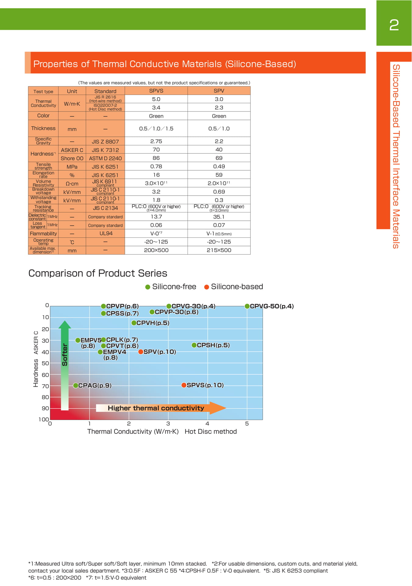
Properties of Thermal Conductive Materials (Silicone-Based)
Test type
Thermal Conductivity
Color
Thickness
Specific Gravity Hardness *1
Tensile strength
Elongation rate
Volume Resistivity Breakdown voltage
Withstanding voltage
Tracking resistance
Dielectric constant 1MHz Loss tangent 1MHz
Flammability Operating temp Available max. dimension *2
(The values are measured values, but not the product specifications or guaranteed.)
Unit
W/m・ K
ー
Standard
JIS R 2616
(Hot-wire method)
ISO22007-2
(Hot Disc method)
ー
SPVS 5.0
3.4 Green
SPV
3.0
2.3
Green mm
ー ASKER C Shore 00 MPa %Ω・ cm kV/mm kV/mm ーーーー℃mm
ー
JIS Z 8807 JIS K 7312 ASTM D 2240 JIS K 6251
JIS K 6251 JIS K 6911 compliant JIS C 2110-1 compliant
JIS C 2110-1 compliant
JIS C 2134
Company standard Company standard UL94 ーー
0.5/1.0/1.5
2.75 70 86 0.78 16 3.0×10 11 3.2
1.8 PLC:0 (600V or higher) (t=4.0mm)
13.7
0.06 V-0 *7 -20~125 200×500
0.5/1.0
2.2 40 69 0.49 59 2.0×10 11 0.69
0.3 PLC:0 (600V or higher) (t=3.0mm)
35.1
0.07 V-1(t0.5mm)
-20~125 215×500
Silicone-Based Thermal Interface Materials
Comparison of Product Series ● Silicone-free ● Silicone-based Hardness ASKER C
0 10 20 30 40 50 60 70 80 90
Softer
●CPVP(p.6) ●CPSS(p.7) ●CPSS(p.7)
●EMPV5 ●CPLK(p.7)
(p.8)
●CPVT(p.6) ●EMPV4
●SPV(p.10)
(p.8)
●CPAG(p.9)
●CPVG-30(p.4) ●CPVP-30(p.6)
●CPVH(p.5) ●CPVH(p.5)
●SPVS(p.10)
Higher thermal 高熱伝導 conductivity
●CPSH(p.5)
●CPVG-50(p.4)
100 0
1 2 3
Thermal Conductivity (W/m・K)
4 5
Hot Disc method
*1:Measured Ultra soft/Super soft/Soft layer, minimum 10mm stacked. *2:For usable dimensions, custom cuts, and material yield, contact your local sales department. *3:0.5F :ASKER C 55 *4:CPSH-F 0.5F : V-0 equivalent. *5:JIS K 6253 compliant *6:t=0.5 : 200×200 *7:t=1.5:V-0 equivalent
Thermal Resistance
3
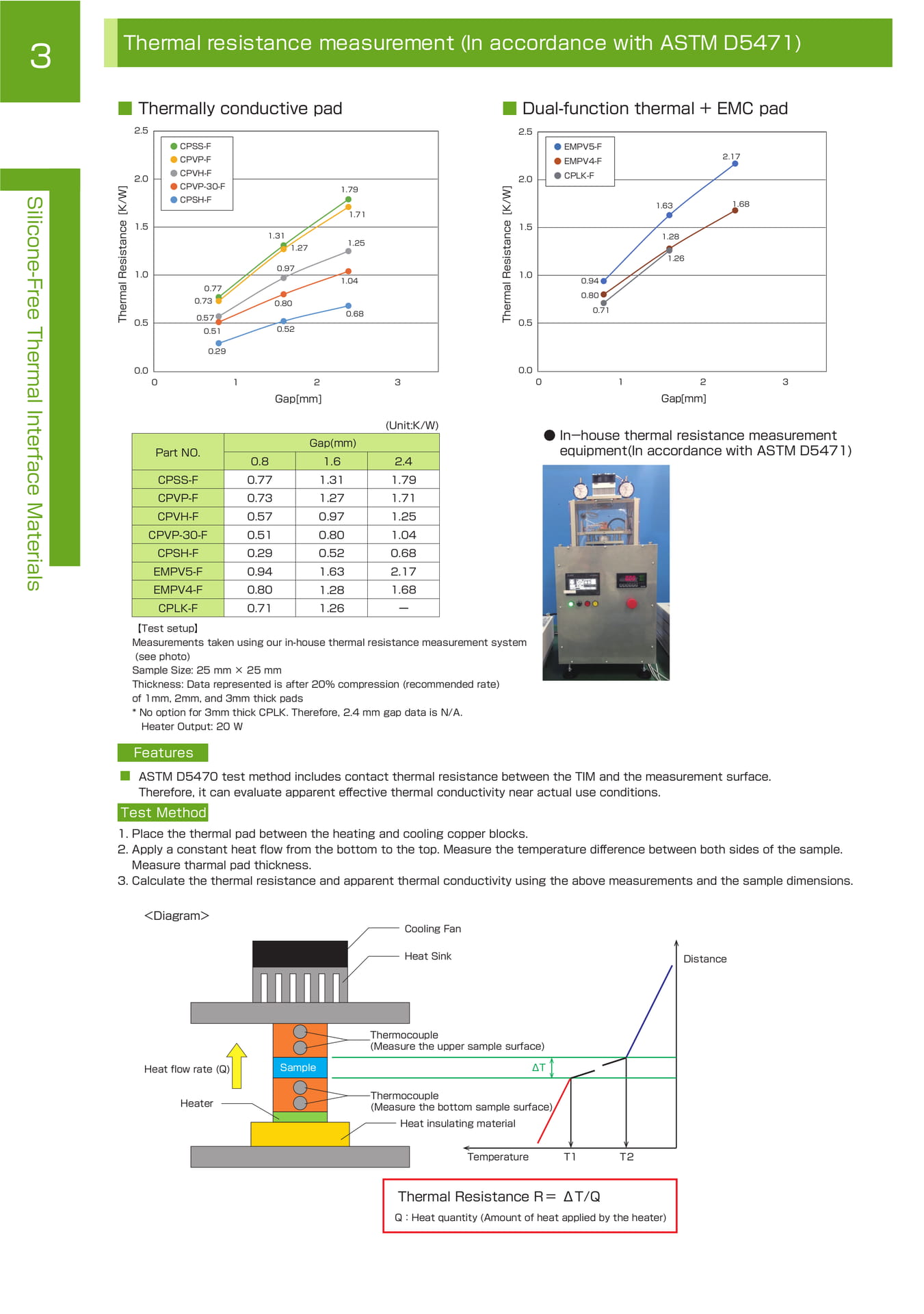
Thermal resistance measurement (In accordance with ASTM D5471) ■ Thermally conductive pad ■ Dual-function thermal + EMC pad
Silicone-Free Thermal Interface Materials
Thermal Resistance [K/W]
2.5 ● CPSS-F ● CPVP-F ● CPVH-F 2.0 ● CPVP-30-F 1.79 ● CPSH-F 1.71
1.5 1.31
1.25
1.27
0.97 1.0
1.04
0.77 0.73
0.80 0.68
0.57 0.5
0.51 0.52
0.29
0.0
0 1 2 3
Gap[mm]
(Unit:K/W)
Gap(mm)
Part NO.
CPSS-F CPVP-F CPVH-F CPVP-30-F CPSH-F EMPV5-F EMPV4-F CPLK-F
0.8 0.77 0.73 0.57 0.51 0.29 0.94 0.80 0.71
1.6 1.31 1.27 0.97 0.80 0.52 1.63 1.28 1.26
2.4 1.79 1.71 1.25 1.04 0.68 2.17 1.68 ー
Thermal Resistance [K/W]
2.5
2.0
1.5
1.0
0.5 ● EMPV5-F ● EMPV4-F ● CPLK-F
0.94 0.80
0.71
1.63
1.28
1.26
2.17
1.68
0.0 0 1 2 3
Gap[mm] ● In-house thermal resistance measurement equipment(In accordance with ASTM D5471)
【 Test setup 】 Measurements taken using our in-house thermal resistance measurement system (see photo) Sample Size: 25 mm × 25 mm Thickness: Data represented is after 20% compression (recommended rate) of 1mm, 2mm, and 3mm thick pads * No option for 3mm thick CPLK. Therefore, 2.4 mm gap data is N/A. Heater Output: 20 W
Features ■ ASTM D5470 test method includes contact thermal resistance between the TIM and the measurement surface. Therefore, it can evaluate apparent effective thermal conductivity near actual use conditions.
Test Method
1.Place the thermal pad between the heating and cooling copper blocks. 2.Apply a constant heat flow from the bottom to the top. Measure the temperature difference between both sides of the sample.
Measure tharmal pad thickness. 3.Calculate the thermal resistance and apparent thermal conductivity using the above measurements and the sample dimensions.
<Diagram> Cooling Fan
Heat Sink Distance
Heat flow rate (Q) Sample
Thermocouple (Measure the upper sample surface)
ΔT
Heater
Thermocouple (Measure the bottom sample surface)
Heat insulating material
Temperature T1
T2
Thermal Resistance R=ΔT/Q
Q:Heat quantity (Amount of heat applied by the heater)
COOLPROVIDE / CPVG
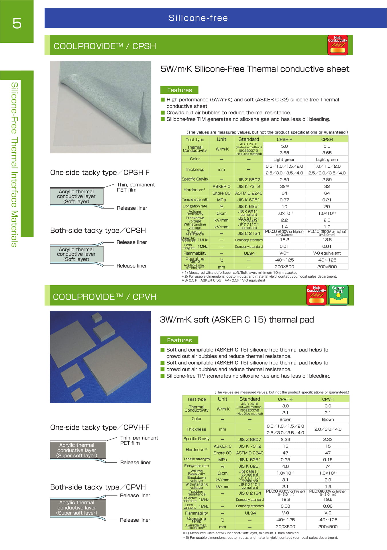
COOLPROVIDE / CPSH
5
Silicone-free
COOLPROVIDE TM / CPSH
High Conductivity
5W/m ・ K Silicone-Free Thermal conductive sheet
Silicone-Free Thermal Interface Materials
One-side tacky type/CPSH-F
Acrylic thermal conductive layer (Soft layer)
Thin, permanent PET film
Release liner
Both-side tacky type/CPSH
Acrylic thermal conductive layer
(Soft layer)
Release liner
Release liner
Features ■ High performance (5W/m・ K) and soft (ASKER C 32) silicone-free Thermal conductive sheet. ■ Crowds out air bubbles to reduce thermal resistance. ■ Silicone-free TIM generates no siloxane gas and has less oil bleeding.
(The values are measured values, but not the product specifications or guaranteed.)
Test type
Thermal
Conductivity
Unit
W/m・ K
Standard
JIS R 2616
(Hot-wire method)
ISO22007-2
(Hot Disc method)
CPSH-F 5.0
3.65
CPSH 5.0
3.65
Color
Thickness
ー mm
ーー
Light green 0.5/1.0/1.5/2.0
Light green 1.0/1.5/2.0
Specific Gravity Hardness *1
ー ASKER C
JIS Z 8807 JIS K 7312
2.5/3.0/3.5/4.0 2.89 32 *3
2.5/3.0/3.5/4.0 2.89 32
Tensile strength
Elongation rate
Volume
Resistivity
Breakdown voltage
Withstanding voltage
Tracking resistance
Dielectric constant 1MHz
Shore 00 MPa %Ω・ cm kV/mm kV/mm ーー
ASTM D 2240 JIS K 6251
JIS K 6251 JIS K 6911 compliant JIS C 2110-1 compliant JIS C 2110-1 compliant
JIS C 2134
Company standard
64 0.37 10 1.0×10 11 2.2
1.4 PLC:0 (600V or higher)
(t=3.0mm)
18.2
64 0.21 20 1.0×10 11 2.0
1.2 PLC:0 (600V or higher)
(t=3.0mm)
18.8
Loss tangent 1MHz ー Company standard 0.01
0.01
Flammability
Operating temp
Available max. dimension *2
ー℃ mm
UL94 ーー V-0 *4 -40~125 200×500
V-0 equivalent -40~125 200×500
*1) Measured Ultra soft/Super soft/Soft layer, minimum 10mm stacked
*2) For usable dimensions, custom cuts, and material yield, contact your local sales department.
*3) 0.5F:ASKER C 55 *4) 0.5F:V-0 equivalent
COOLPROVIDE TM / CPVH
High Conductivity
Super Soft
3W/m ・ K soft (ASKER C 15) thermal pad
Features ■ Soft and compilable (ASKER C 15) silicone free thermal pad helps to crowd out air bubbles and reduce thermal resistance. ■ Soft and compilable (ASKER C 15) silicone free thermal pad helps to ■ crowd out air bubbles and reduce thermal resistance. ■ Silicone-free TIM generates no siloxane gas and has less oil bleeding.
One-side tacky type/CPVH-F
Acrylic thermal conductive layer (Super soft layer)
Thin, permanent PET film
Release liner
Both-side tacky type/CPVH
Acrylic thermal conductive layer (Super soft layer)
Release liner
Release liner
(The values are measured values, but not the product specifications or guaranteed.)
Test type
Thermal
Conductivity
Unit
W/m・ K
Standard
JIS R 2616
(Hot-wire method)
ISO22007-2
(Hot Disc method)
CPVH-F 3.0
2.1
CPVH 3.0
2.1
Color
Thickness
ー mm
ーー
Brown 0.5/1.0/1.5/2.0
Brown
2.0/3.0/4.0
Specific Gravity Hardness *1
ー ASKER C
JIS Z 8807 JIS K 7312
2.5/3.0/3.5/4.0 2.33 15
2.33 15
Tensile strength
Elongation rate Volume
Resistivity
Breakdown voltage
Withstanding voltage
Tracking resistance
Dielectric constant 1MHz
Shore 00 MPa %Ω・ cm kV/mm kV/mm ーー
ASTM D 2240 JIS K 6251
JIS K 6251 JIS K 6911 compliant JIS C 2110-1 compliant JIS C 2110-1 compliant
JIS C 2134 Company standard
47 0.25 4.0 1.0×10 11 3.1
2.1 PLC:0 (600V or higher)
(t=3.0mm)
18.2
47 0.15 74 1.0×10 11 2.9
1.9
PLC:0(600V or higher)
(t=3.0mm)
19.6
Loss tangent 1MHz ー Company standard 0.08
0.08
Flammability Operating temp Available max. dimension *2
ー℃ mm
UL94 ーー
V-0 -40~125 200×500
V-0 -40~125 200×500
*1) Measured Ultra soft/Super soft/Soft layer, minimum 10mm stacked
*2) For usable dimensions, custom cuts, and material yield, contact your local sales department.
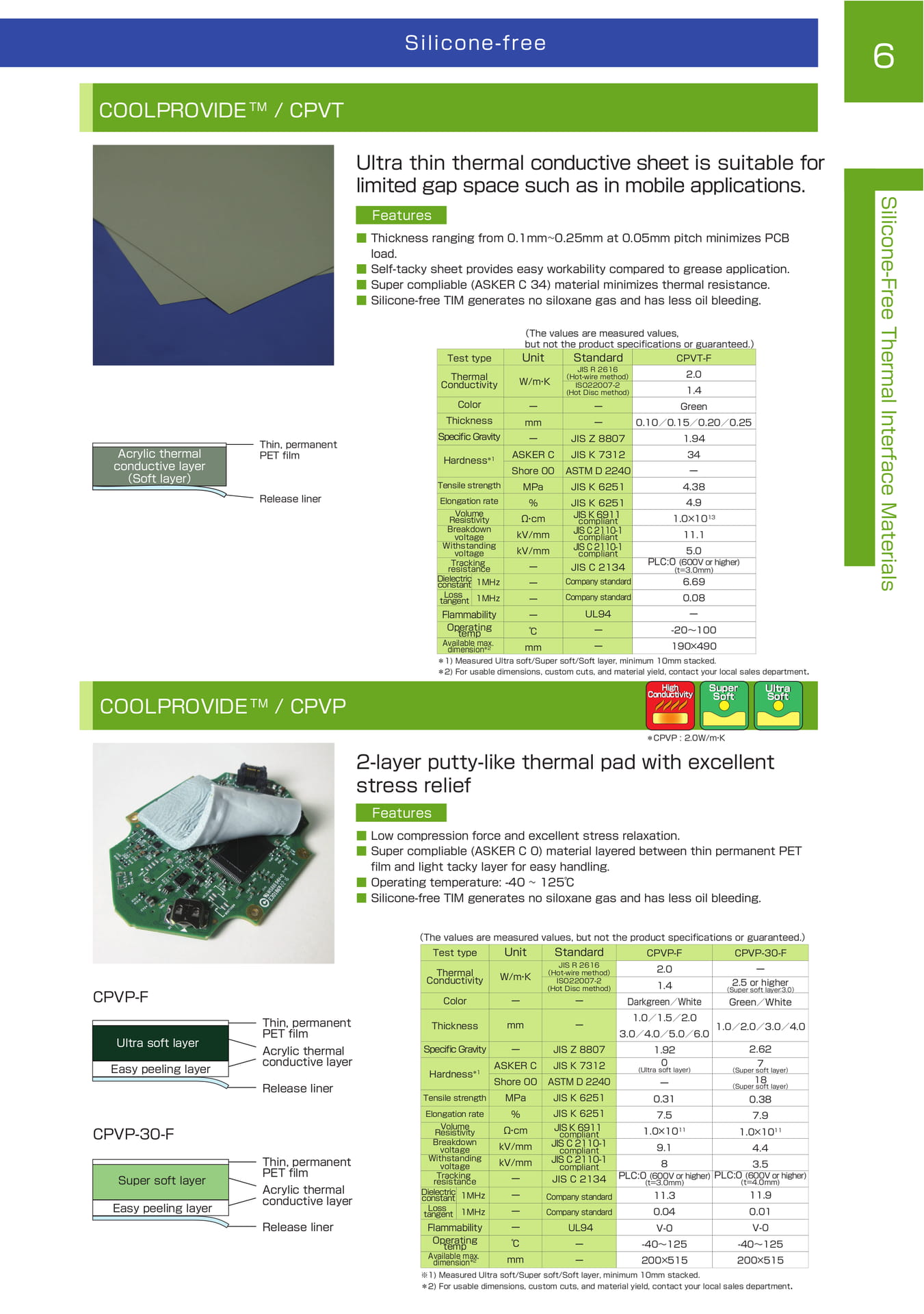
COOLPROVIDE / CPVT
Silicone-free
6
COOLPROVIDE TM / CPVT
Acrylic thermal conductive layer (Soft layer)
Thin, permanent PET film
Release liner
COOLPROVIDE TM / CPVP
Ultra thin thermal conductive sheet is suitable for limited gap space such as in mobile applications.
Features ■ Thickness ranging from 0.1mm~0.25mm at 0.05mm pitch minimizes PCB load. ■ Self-tacky sheet provides easy workability compared to grease application. ■ Super compliable (ASKER C 34) material minimizes thermal resistance. ■ Silicone-free TIM generates no siloxane gas and has less oil bleeding.
Test type Thermal Conductivity
Color Thickness Specific Gravity Hardness *1
Tensile strength
Elongation rate Volume Resistivity
Breakdown voltage
Withstanding voltage
Tracking resistance
Dielectric constant 1MHz
(The values are measured values, but not the product specifications or guaranteed.)
Unit
W/m・ K
Standard
JIS R 2616
(Hot-wire method)
ISO22007-2
(Hot Disc method)
CPVT-F
2.0
1.4
ー mm
ー
ASKER C
Shore 00
MPa
ーー JIS Z 8807 JIS K 7312 ASTM D 2240 JIS K 6251
Green
0.10/0.15/0.20/0.25
1.94
34
ー
4.38
%Ω・ cm kV/mm kV/mm ーー
JIS K 6251 JIS K 6911 compliant JIS C 2110-1 compliant JIS C 2110-1 compliant
JIS C 2134 Company standard
4.9 1.0×10 13 11.1
5.0 PLC:0 (600V or higher) (t=3.0mm)
6.69
Loss tangent 1MHz ー Company standard
0.08
Flammability ー
UL94
ー
Operating temp
℃
ー
-20~100
Available max. dimension *2 mm
ー
190×490
*1) Measured Ultra soft/Super soft/Soft layer, minimum 10mm stacked.
*2) For usable dimensions, custom cuts, and material yield, contact your local sales department.
High Conductivity
Super Soft
Ultra Soft
Silicone-Free Thermal Interface Materials
2-layer putty-like thermal pad with excellent stress relief
■■■■ Features
*CPVP : 2.0W/m・ K
Low compression force and excellent stress relaxation. Super compliable (ASKER C 0) material layered between thin permanent PET film and light tacky layer for easy handling. Operating temperature: -40 ~ 125℃ Silicone-free TIM generates no siloxane gas and has less oil bleeding.
CPVP-F
Ultra soft layer Easy peeling layer
CPVP-30-F
Super soft layer
Easy peeling layer
Thin, permanent PET film
Acrylic thermal conductive layer
Release liner
Thin, permanent PET film
Acrylic thermal conductive layer
Release liner
(The values are measured values, but not the product specifications or guaranteed.)
Test type
Thermal
Conductivity
Color
Unit
W/m・ K
ー
Standard
JIS R 2616
(Hot-wire method)
ISO22007-2
(Hot Disc method)
ー
CPVP-F 2.0
1.4 Darkgreen/White 1.0/1.5/2.0
CPVP-30-F
ー
2.5 or higher
(Super soft layer:3.0)
Green/White
Thickness mm
ー
1.0/2.0/3.0/4.0
3.0/4.0/5.0/6.0
Specific Gravity Hardness *1
ー ASKER C Shore 00
JIS Z 8807 JIS K 7312 ASTM D 2240
1.92
0
(Ultra soft layer)
ー
2.62 7 (Super soft layer)
18
(Super soft layer)
Tensile strength
Elongation rate Volume
Resistivity Breakdown voltage
Withstanding voltage
MPa %Ω・ cm kV/mm kV/mm
JIS K 6251 JIS K 6251 JIS K 6911 compliant JIS C 2110-1 compliant JIS C 2110-1 compliant
0.317.5 1.0×10 11 9.18
0.38 7.9 1.0×10 11 4.4 3.5
Tracking resistance ー JIS C 2134 PLC:0 (600V or higher) PLC:0 (600V or higher)
(t=3.0mm)
(t=4.0mm)
Dielectric constant 1MHz ー Company standard 11.3
11.9
Loss tangent 1MHz ー Company standard 0.04
0.01
Flammability Operating temp Available max. dimension *2
ー℃mm
UL94 ーー
V-0 -40~125 200×515
V-0 -40~125 200×515
※1) Measured Ultra soft/Super soft/Soft layer, minimum 10mm stacked. *2) For usable dimensions, custom cuts, and material yield, contact your local sales department.
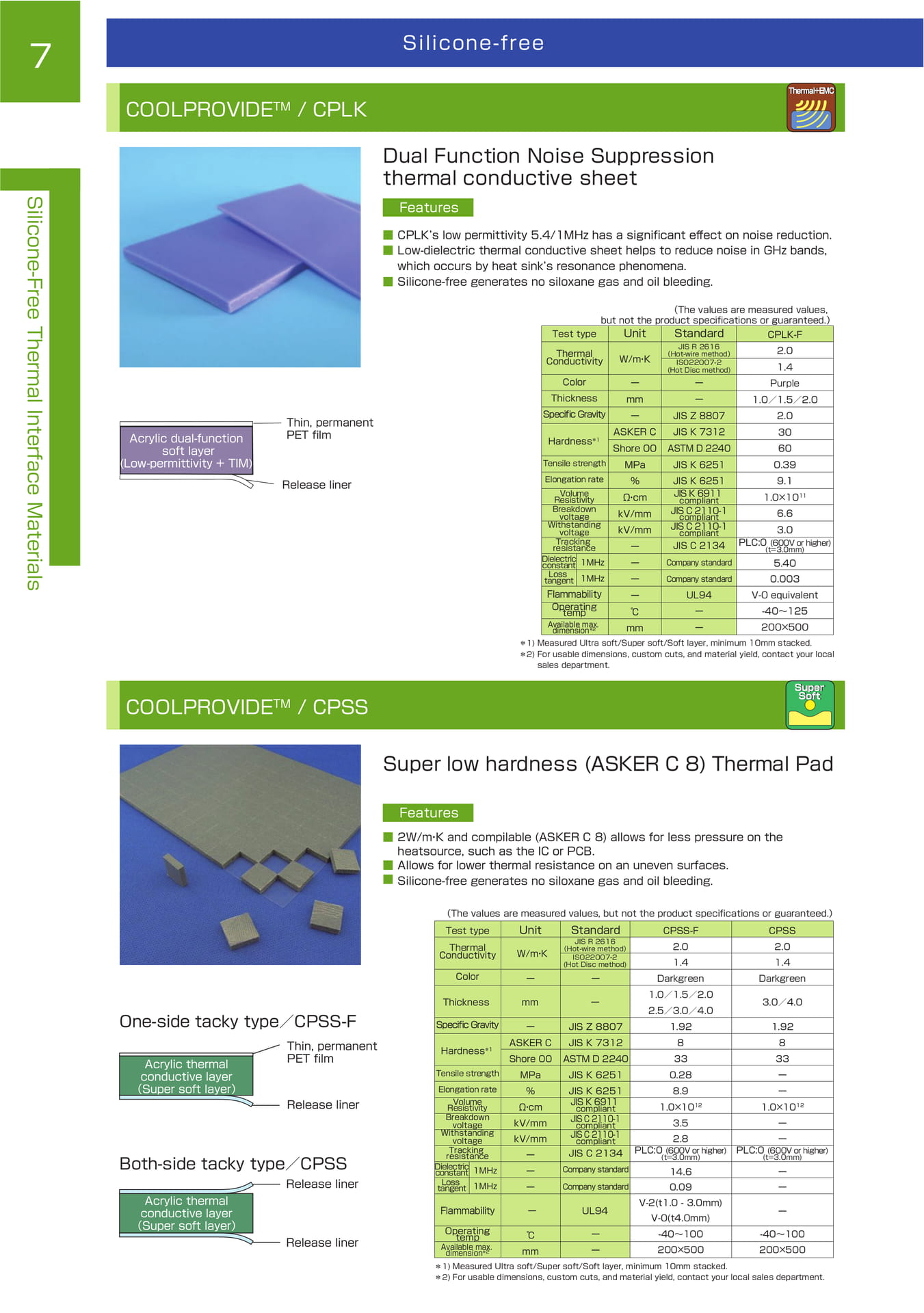
COOLPROVIDE / CPLK
7
Silicone-free
COOLPROVIDE TM / CPLK
Thermal+EMC
Dual Function Noise Suppression thermal conductive sheet
Silicone-Free Thermal Interface Materials
Acrylic dual-function soft layer (Low-permittivity + TIM)
Thin, permanent PET film
Release liner
Features ■ CPLK’s low permittivity 5.4/1MHz has a significant effect on noise reduction. ■ Low-dielectric thermal conductive sheet helps to reduce noise in GHz bands, which occurs by heat sink’s resonance phenomena. ■ Silicone-free generates no siloxane gas and oil bleeding.
(The values are measured values, but not the product specifications or guaranteed.)
Test type
Thermal
Conductivity
Unit
W/m・ K
Standard
JIS R 2616
(Hot-wire method)
ISO22007-2
(Hot Disc method)
CPLK-F 2.0
1.4
Color Thickness Specific Gravity Hardness *1
Tensile strength Elongation rate Volume
Resistivity Breakdown voltage Withstanding voltage
Tracking resistance
Dielectric constant 1MHz
ーmmー ASKER C Shore 00 MPa %Ω・ cm kV/mm kV/mm ーー
ーー JIS Z 8807 JIS K 7312 ASTM D 2240 JIS K 6251
JIS K 6251 JIS K 6911 compliant JIS C 2110-1 compliant JIS C 2110-1 compliant
JIS C 2134
Company standard
Purple 1.0/1.5/2.0 2.0 30 60 0.39 9.1 1.0×10 11 6.6
3.0 PLC:0 (600V or higher)
(t=3.0mm)
5.40
Loss tangent 1MHz ー Company standard 0.003
Flammability Operating temp Available max. dimension *2
ー℃mm
UL94 ーー
V-0 equivalent -40~125 200×500 *1) Measured Ultra soft/Super soft/Soft layer, minimum 10mm stacked. *2) For usable dimensions, custom cuts, and material yield, contact your local sales department.
COOLPROVIDE TM / CPSS
Super Soft
Super low hardness (ASKER C 8) Thermal Pad
Features ■ 2W/m・ K and compilable (ASKER C 8) allows for less pressure on the heatsource, such as the IC or PCB. ■ Allows for lower thermal resistance on an uneven surfaces. ■ Silicone-free generates no siloxane gas and oil bleeding.
One-side tacky type/CPSS-F
Acrylic thermal conductive layer (Super soft layer)
Thin, permanent PET film
Release liner
Both-side tacky type/CPSS
Acrylic thermal conductive layer (Super soft layer)
Release liner
Release liner
(The values are measured values, but not the product specifications or guaranteed.)
Test type
Thermal
Conductivity
Color
Thickness
Unit
W/m・ K
ー mm
Standard
JIS R 2616
(Hot-wire method)
ISO22007-2
(Hot Disc method)
ーー
CPSS-F 2.0
1.4 Darkgreen 1.0/1.5/2.0
CPSS 2.0
1.4 Darkgreen
3.0/4.0
Specific Gravity Hardness *1
ー ASKER C
JIS Z 8807 JIS K 7312
2.5/3.0/4.0 1.92 8
1.92 8
Tensile strength
Elongation rate Volume
Resistivity Breakdown voltage Withstanding voltage
Tracking resistance
Dielectric constant 1MHz
Shore 00 MPa %Ω・ cm kV/mm kV/mm ーー
ASTM D 2240 JIS K 6251
JIS K 6251 JIS K 6911 compliant JIS C 2110-1 compliant JIS C 2110-1 compliant
JIS C 2134
Company standard
33 0.28 8.9 1.0×10 12 3.5
2.8 PLC:0 (600V or higher)
(t=3.0mm)
14.6
33 ーー 1.0×10 12 ーー PLC:0 (600V or higher)
(t=3.0mm)
ー
Loss tangent 1MHz ー Company standard 0.09 V-2(t1.0 - 3.0mm)
ー
Flammability ー UL94
V-0(t4.0mm)
ー
Operating temp Available max. dimension *2
℃ mm
ーー
-40~100 200×500
-40~100 200×500 *1) Measured Ultra soft/Super soft/Soft layer, minimum 10mm stacked. *2) For usable dimensions, custom cuts, and material yield, contact your local sales department.
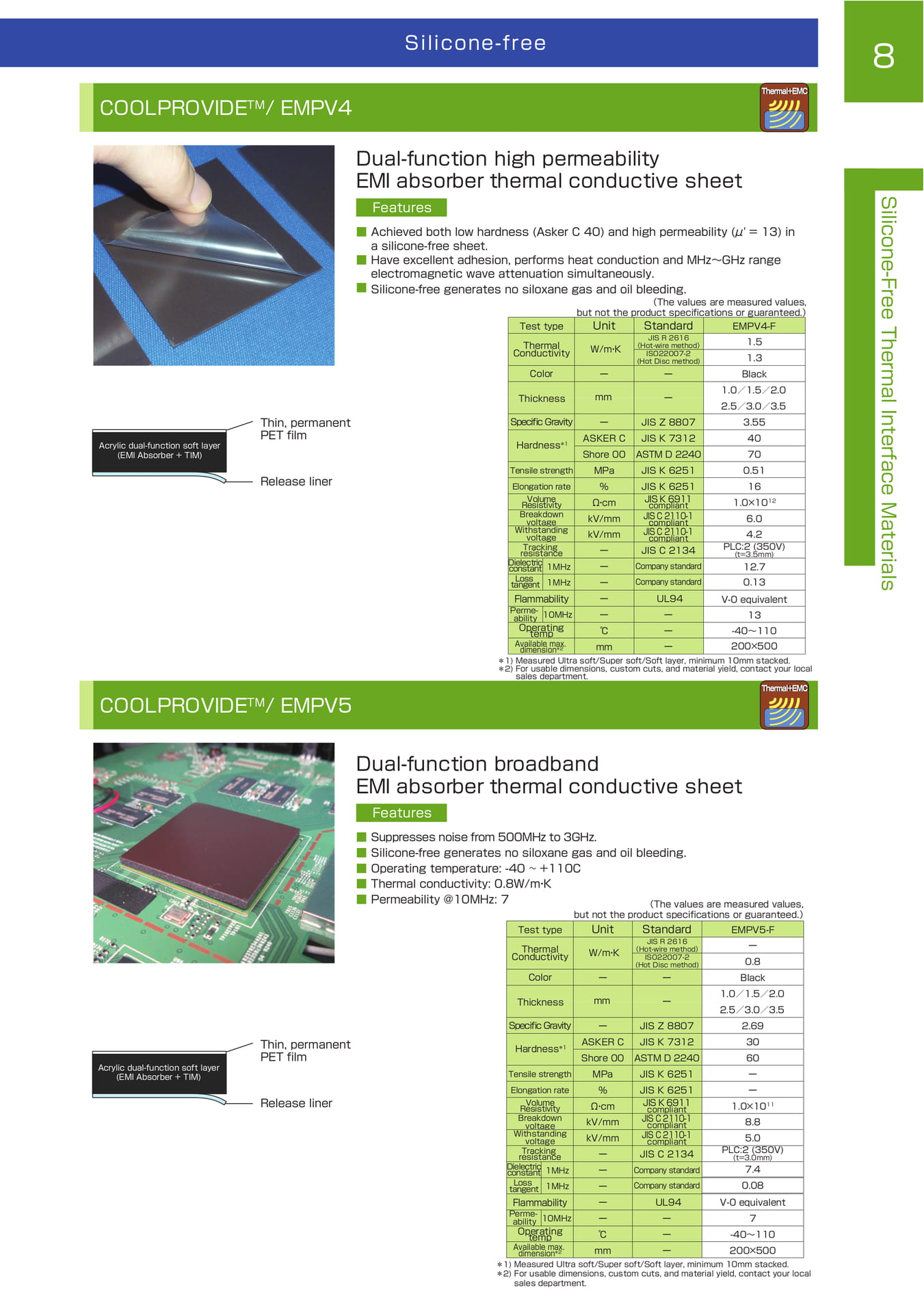
COOLPROVIDE / EMPV
Silicone-free
8
COOLPROVIDE TM / EMPV4
Thermal+EMC
Acrylic dual-function soft layer (EMI Absorber + TIM)
Thin, permanent PET film
Release liner
COOLPROVIDE TM / EMPV5
Dual-function high permeability EMI absorber thermal conductive sheet
Features ■ Achieved both low hardness (Asker C 40) and high permeability (μ' = 13) in a silicone-free sheet. ■ Have excellent adhesion, performs heat conduction and MHz~GHz range electromagnetic wave attenuation simultaneously. ■ Silicone-free generates no siloxane gas and oil bleeding.
(The values are measured values, but not the product specifications or guaranteed.)
Test type Unit Standard EMPV4-F
Thermal Conductivity
Color
Specific Gravity Hardness *1
Tensile strength
Elongation rate Volume Resistivity
Breakdown voltage Withstanding voltage
Tracking resistance
Dielectric constant 1MHz Loss tangent 1MHz
W/m ・ K
ー
ー ASKER C Shore 00 MPa %Ω・ cm kV/mm kV/mm ーーー
JIS R 2616 (Hot-wire method)
ISO22007-2 (Hot Disc method)
ー
Thickness mmー
JIS Z 8807 JIS K 7312 ASTM D 2240 JIS K 6251
JIS K 6251 JIS K 6911 compliant JIS C 2110-1
compliant JIS C 2110-1 compliant
JIS C 2134
Company standard Company standard
1.5 1.3 Black 1.0/1.5/2.0 2.5/3.0/3.5 3.55 40 70 0.51 16 1.0×10 12 6.0
4.2
PLC:2 (350V) (t=3.5mm)
12.7
0.13
Flammability
Permeability ーー
UL94
ー
V-0 equivalent
13
Operating temp Available max. dimension *2
℃ mm
ーー
-40~110
200×500 *1) Measured Ultra soft/Super soft/Soft layer, minimum 10mm stacked. *2) For usable dimensions, custom cuts, and material yield, contact your local sales department.
Thermal+EMC
Silicone-Free Thermal Interface Materials
Dual-function broadband EMI absorber thermal conductive sheet
Features
Acrylic dual-function soft layer (EMI Absorber + TIM)
Thin, permanent PET film
Release liner
■■■■■ Suppresses noise from 500MHz to 3GHz. Silicone-free generates no siloxane gas and oil bleeding. Operating temperature: -40 ~ +110C Thermal conductivity: 0.8W/m ・ K Permeability @10MHz: 7
Test type Thermal Conductivity
Color
Specific Gravity Hardness *1
Tensile strength
Elongation rate Volume Resistivity Breakdown voltage Withstanding voltage
Tracking resistance
Dielectric constant 1MHz Loss tangent 1MHz
(The values are measured values, but not the product specifications or guaranteed.)
Unit Standard EMPV5-F
W/m ・ K
ー
ー ASKER C Shore 00 MPa %Ω・ cm kV/mm kV/mm ーーー
JIS R 2616 (Hot-wire method)
ISO22007-2 (Hot Disc method)
ー
Thickness mmー
JIS Z 8807 JIS K 7312 ASTM D 2240 JIS K 6251
JIS K 6251 JIS K 6911 compliant JIS C 2110-1 compliant JIS C 2110-1 compliant
JIS C 2134
Company standard Company standard
ー0.8 Black 1.0/1.5/2.0 2.5/3.0/3.5 2.693060ーー 1.0×10 11 8.8
5.0
PLC:2 (350V) (t=3.0mm)
7.4
0.08
Flammability
Permeability 10MHz
ーー
UL94
ー
V-0 equivalent
7
Operating temp Available max. dimension *2
℃ mm
ーー
-40~110
200×500 *1) Measured Ultra soft/Super soft/Soft layer, minimum 10mm stacked. *2) For usable dimensions, custom cuts, and material yield, contact your local sales department.
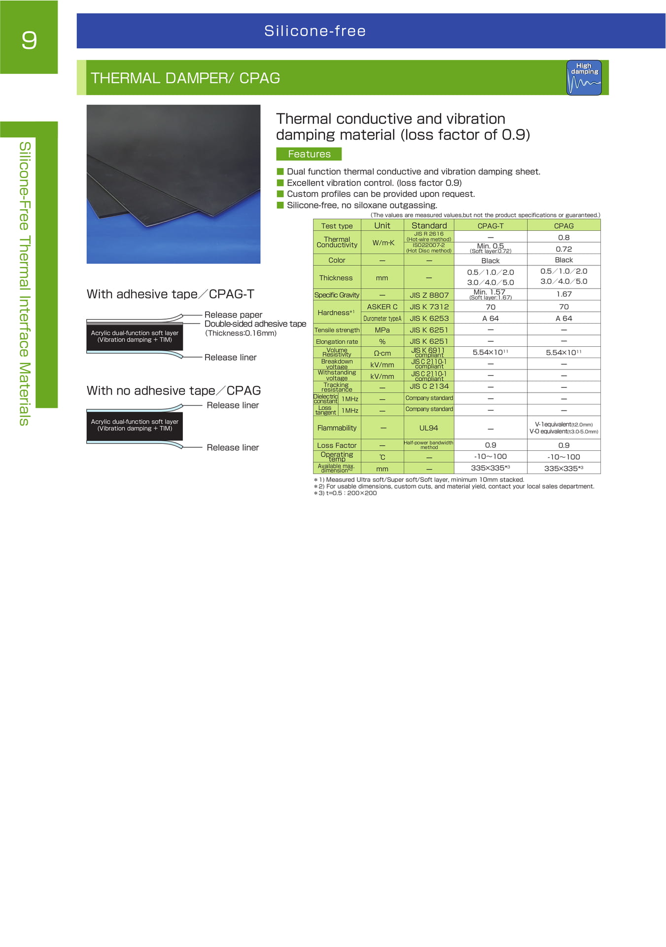
THERMAL DAMPER / CPAG
9
Silicone-free
THERMAL DAMPER/ CPAG
High damping
Silicone-Free Thermal Interface Materials
With adhesive tape/CPAG-T
Acrylic dual-function soft layer (Vibration damping + TIM)
Release paper Double-sided adhesive tape
(Thickness:0.16mm)
Release liner
With no adhesive tape/CPAG
Acrylic dual-function soft layer (Vibration damping + TIM)
Release liner
Thermal conductive and vibration damping material (loss factor of 0.9)
Features ■ Dual function thermal conductive and vibration damping sheet. ■ Excellent vibration control. (loss factor 0.9) ■ Custom profiles can be provided upon request. ■ Silicone-free, no siloxane outgassing.
(The values are measured values,but not the product specifications or guaranteed.)
Test type
Thermal
Conductivity
Color
Thickness
Specific Gravity Hardness *1
Unit
W/m・ K
ー mm
ー
ASKER C
Standard
JIS R 2616
(Hot-wire method)
ISO22007-2
(Hot Disc method)
ーー
JIS Z 8807
JIS K 7312
CPAG-T
ー
Min. 0.5
(Soft layer:0.72)
Black 0.5/1.0/2.0 3.0/4.0/5.0 Min. 1.57
(Soft layer:1.67)
70
CPAG
0.8
0.72
Black
0.5/1.0/2.0
3.0/4.0/5.0
1.67
70
Tensile strength
Elongation rate
Volume
Resistivity
Breakdown voltage
Withstanding voltage
Tracking resistance
Dielectric constant 1MHz
Durometer typeA
MPa
%Ω・ cm kV/mm kV/mm
ーー
JIS K 6253
JIS K 6251
JIS K 6251
JIS K 6911 compliant
JIS C 2110-1 compliant
JIS C 2110-1 compliant
JIS C 2134
Company standard
A 64ーー 5.54×10 11 ーーーー
A 64
ーー 5.54×10 11
ーーーー
Loss tangent 1MHz ー Company standard
ー
ー Flammability ー UL94 ー
V-1equivalent(t2.0mm) V-0 equivalent(t3.0-5.0mm)
Release liner
Loss Factor
Operating temp
Available max. dimension *2
ー
℃ mm
Half-power bandwidth method
ーー
0.9 -10~100 335×335* 3
0.9
-10~100 335×335* 3 *1) Measured Ultra soft/Super soft/Soft layer, minimum 10mm stacked. *2) For usable dimensions, custom cuts, and material yield, contact your local sales department.
*3) t=0.5:200×200
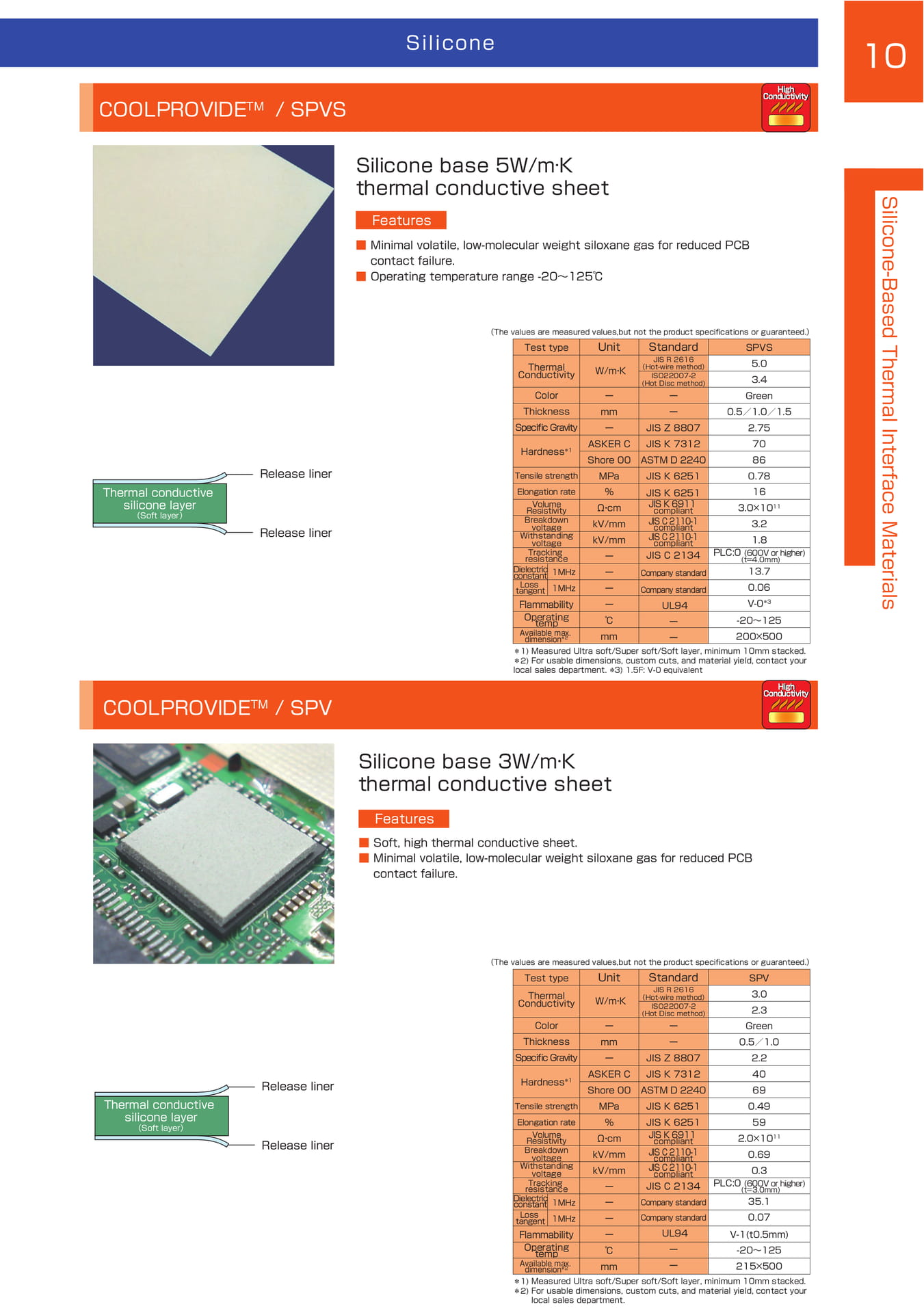
COOLPROVIDE / SPVS
Silicone
10 COOLPROVIDE TM
/ SPVS
High Conductivity
Silicone base 5W/m·K thermal conductive sheet
Thermal conductive silicone layer (Soft layer)
Release liner
Release liner
Features ■ Minimal volatile, low-molecular weight siloxane gas for reduced PCB contact failure. ■ Operating temperature range -20~125℃
(The values are measured values,but not the product specifications or guaranteed.)
Test type
Thermal
Conductivity
Color Thickness Specific Gravity Hardness *1
Unit
W/m・ K
ーmmー ASKER C
Standard
JIS R 2616
(Hot-wire method)
ISO22007-2
(Hot Disc method)
ーー JIS Z 8807 JIS K 7312
SPVS 5.0
3.4 Green 0.5/1.0/1.5 2.75 70
Tensile strength
Elongation rate Volume
Resistivity Breakdown voltage Withstanding voltage
Tracking resistance
Dielectric constant 1MHz
Shore 00 MPa %Ω・ cm kV/mm kV/mm ーー
ASTM D 2240 JIS K 6251
JIS K 6251 JIS K 6911 compliant JIS C 2110-1 compliant JIS C 2110-1 compliant
JIS C 2134
Company standard
86 0.78 16 3.0×10 11 3.2
1.8 PLC:0 (600V or higher)
(t=4.0mm)
13.7
Loss tangent 1MHz ー Company standard 0.06
Flammability Operating temp Available max. dimension *2
ー℃mm
UL94 ーー V-0*3
-20~125 200×500 *1) Measured Ultra soft/Super soft/Soft layer, minimum 10mm stacked. *2) For usable dimensions, custom cuts, and material yield, contact your local sales department. *3) 1.5F: V-0 equivalent
Silicone-Based Thermal Interface Materials
COOLPROVIDE TM / SPV
High Conductivity
Silicone base 3W/m·K thermal conductive sheet
Features ■ Soft, high thermal conductive sheet. ■ Minimal volatile, low-molecular weight siloxane gas for reduced PCB contact failure.
Thermal conductive silicone layer (Soft layer)
Release liner
Release liner
(The values are measured values,but not the product specifications or guaranteed.)
Test type
Thermal
Conductivity
Color Thickness Specific Gravity Hardness *1
Unit
W/m・ K
ーmmー ASKER C
Standard
JIS R 2616
(Hot-wire method)
ISO22007-2
(Hot Disc method)
ーー JIS Z 8807 JIS K 7312
SPV 3.0
2.3 Green 0.5/1.0 2.2 40
Tensile strength
Elongation rate Volume
Resistivity Breakdown voltage Withstanding voltage
Tracking resistance
Dielectric constant 1MHz
Shore 00 MPa %Ω・ cm kV/mm kV/mm ーー
ASTM D 2240 JIS K 6251
JIS K 6251 JIS K 6911 compliant JIS C 2110-1 compliant JIS C 2110-1 compliant
JIS C 2134
Company standard
69 0.49 59 2.0×10 11 0.69
0.3 PLC:0 (600V or higher)
(t=3.0mm)
35.1
Loss tangent 1MHz ー Company standard 0.07
Flammability Operating temp Available max. dimension *2
ー℃mm
UL94 ーー
V-1(t0.5mm) -20~125 215×500 *1) Measured Ultra soft/Super soft/Soft layer, minimum 10mm stacked. *2) For usable dimensions, custom cuts, and material yield, contact your local sales department.
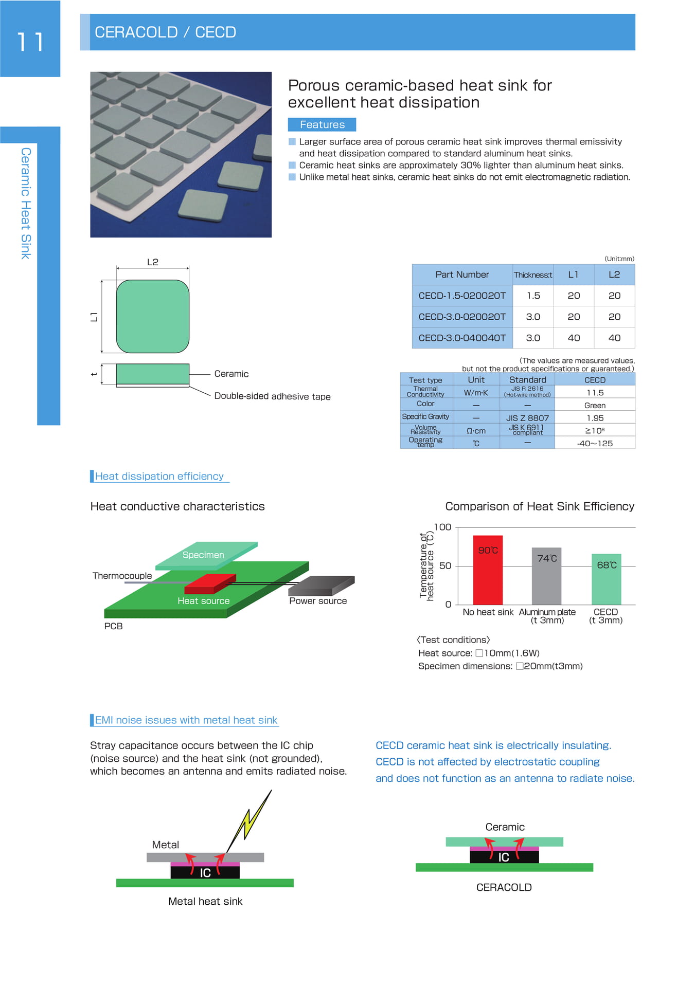
CERACOLD / CECD
11
CERACOLD / CECD
Porous ceramic-based heat sink for excellent heat dissipation
Features
Ceramic Heat Sink
L2 ■ Larger surface area of porous ceramic heat sink improves thermal emissivity and heat dissipation compared to standard aluminum heat sinks. ■ Ceramic heat sinks are approximately 30% lighter than aluminum heat sinks. ■ Unlike metal heat sinks, ceramic heat sinks do not emit electromagnetic radiation.
Part Number Thickness:t
L1
(Unit:mm)
L2
CECD-1.5-020020T 1.5
20 20
L1
CECD-3.0-020020T 3.0
20 20
CECD-3.0-040040T 3.0
40 40 t
Ceramic
Double-sided adhesive tape
Test type Thermal Conductivity
Color
Specific Gravity Volume Resistivity Operating temp
(The values are measured values, but not the product specifications or guaranteed.)
Unit
W/m・ K
ーーΩ・ cm
℃
Standard
JIS R 2616
(Hot-wire method)
ー
JIS Z 8807 JIS K 6911 compliant
ー
CECD 11.5 Green 1.95 ≧10 8 -40~125
Heat dissipation efficiency
Heat conductive characteristics Comparison of Heat Sink Efficiency
Thermocouple
PCB
Specimen
Heat source
Power source
Temperature of heat source(℃)
100
50
0
90℃ 90℃
No heat sink
74℃
Aluminum plate (t 3mm)
〈 Test conditions 〉 Heat source: □10mm(1.6W) Specimen dimensions: □20mm(t3mm)
68℃
CECD (t 3mm)
EMI noise issues with metal heat sink
Stray capacitance occurs between the IC chip (noise source) and the heat sink (not grounded), which becomes an antenna and emits radiated noise.
CECD ceramic heat sink is electrically insulating. CECD is not affected by electrostatic coupling and does not function as an antenna to radiate noise.
Ceramic
Metal
IC
Metal heat sink
IC
CERACOLD
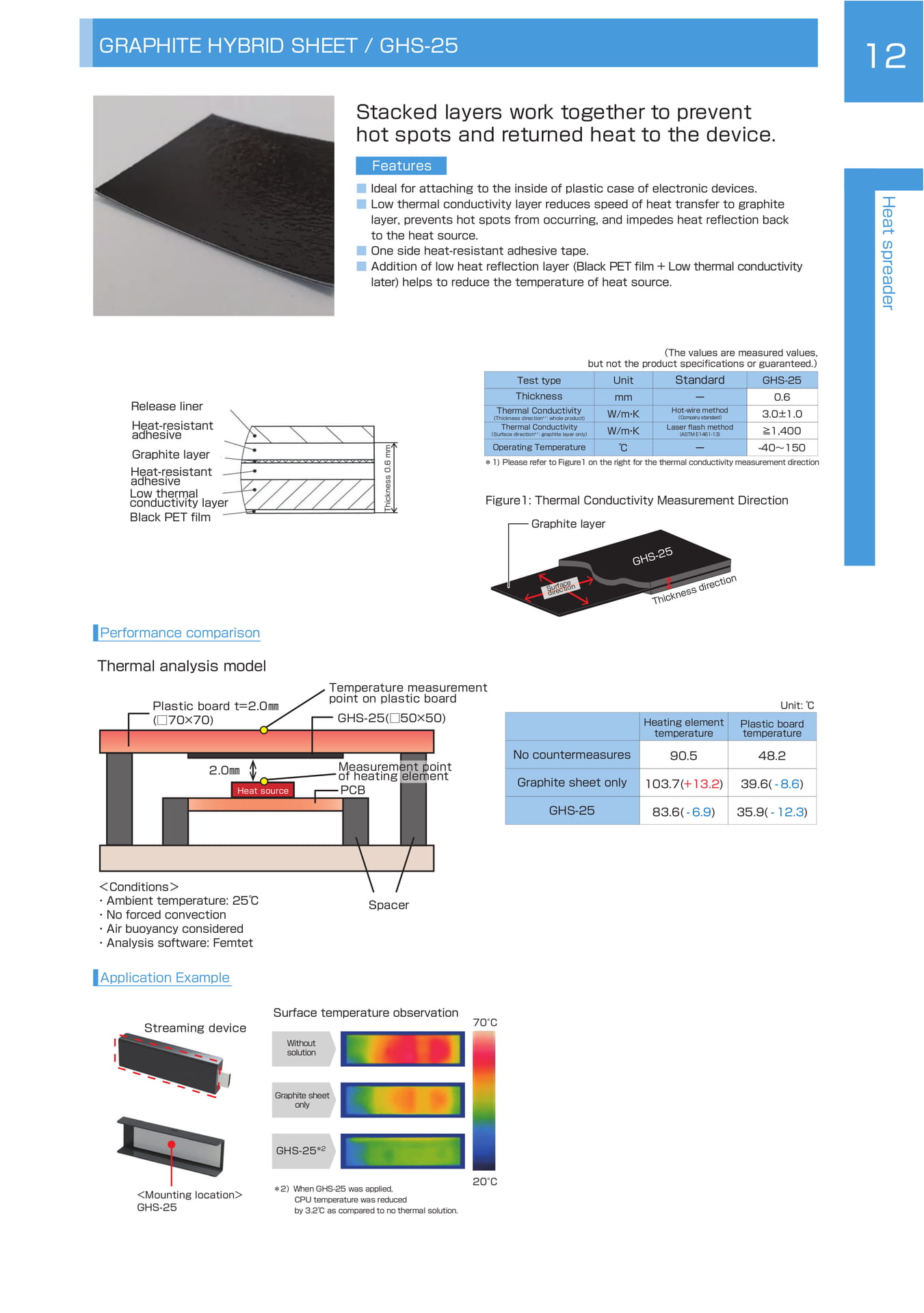
GRAPHITE HYBRID SHEET
GRAPHITE HYBRID SHEET / GHS-25
12
Stacked layers work together to prevent hot spots and returned heat to the device.
Features
■■■■ Ideal for attaching to the inside of plastic case of electronic devices. Low thermal conductivity layer reduces speed of heat transfer to graphite layer, prevents hot spots from occurring, and impedes heat reflection back to the heat source. One side heat-resistant adhesive tape. Addition of low heat reflection layer (Black PET film + Low thermal conductivity later) helps to reduce the temperature of heat source.
Heat spreader
Release liner Heat-resistant adhesive
Graphite layer Heat-resistant adhesive Low thermal conductivity layer
Black PET film
Thickness 0.6 mm
(The values are measured values, but not the product specifications or guaranteed.)
Test type Thickness
Thermal Conductivity
(Thickness direction *1:whole product)
Unit mm W/m・ K
Standard
ー
Hot-wire method
(Company standard)
GHS-25 0.6 3.0±1.0
Thermal Conductivity
W/m・ K
Laser flash method
(ASTM E1461-13)≧1,400
Operating Temperature ℃
ー
-40~150
(Surface direction *1:graphite layer only)
*1) Please refer to Figure1 on the right for the thermal conductivity measurement direction
Figure1: Thermal Conductivity Measurement Direction Graphite layer
Surface direction
GHS-25
Thickness direction
Performance comparison
Thermal analysis model
Plastic board t=2.0 ㎜ (□70×70)
Temperature measurement point on plastic board
GHS-25(□50×50)
Heating element temperature
Unit: ℃
Plastic board temperature
2.0㎜
Heat source
Measurement point of heating element PCB
No countermeasures
Graphite sheet only
90.5
103.7(+13.2)
48.2
39.6( - 8.6)
GHS-25 83.6( - 6.9)
35.9( - 12.3)
<Conditions>・ Ambient temperature: 25℃・ No forced convection ・ Air buoyancy considered ・ Analysis software: Femtet
Spacer
Application Example
Streaming device
Surface temperature observation
Without solution
70°C
Graphite sheet only GHS-25 *2
<Mounting location> GHS-25
*2)When GHS-25 was applied, CPU temperature was reduced by 3.2℃ as compared to no thermal solution.
20°C

HEAT SPREADER SHEET
13
HEAT SPREADER SHEET / HSD
Thin and flexible heat spreading sheet for superior thermal management
Heat spreader
■■■■ Features
Aluminum heat spreader material with excellent thermal conductivity. (221 W/m·K) Spreads heat away from hot spots to cooler areas to prevent components from overheating. Optional electrically insulating mylar (PET) layer can be applied upon request. Ideal thermal solution for hot spots on space conscious applications such as mobile devices, tablets, routers, video streaming devices, etc.
HSD-0.22
HSD-0.30
Aluminum foil(100μm) Adhesive layer(120μm)
Release paper
Aluminum foil(200μm) Adhesive layer(100μm) Release paper
(The values are measured values, but not the product specifications or guaranteed.)
Test type Unit
Standard HSD-0.22
HSD-0.30
Thickness
Surface Thermal Conductivity
Adhesion mm W/m・ K N/25mm
ー
JIS R 2616 (Hot-wire method)
JIS Z 0237:2009
0.220.30 221(aluminum)
>16>11
Flammability ー
UL ー
ー
Operating temp ℃
ー -20~100
Heat Dissipation Effect heat distribution
No heat sink HSD-0.22
HSD-0.30
Test Sample ①②③
①②③
PET film(30μm) Aluminum foil(100μm) Adhesive layer(120μm)
PET film(30μm) Aluminum foil(200μm) Adhesive layer(100μm)
Testing method HSD Series Heat Dissipation Effect
Thermocouple
Thermography
Specimen
Heat source
Power source
Temperature of heat source(℃)
90 80 70 60 50 40 30 20 10
83.8
59.6 59.3
PCB
0 No heat spreader HSD-0.22
HSD-0.30
<Test conditions> Heat source:□25mm(1.5W) Specimen dimensions:□50mm
Terminologies
Terminologies
14
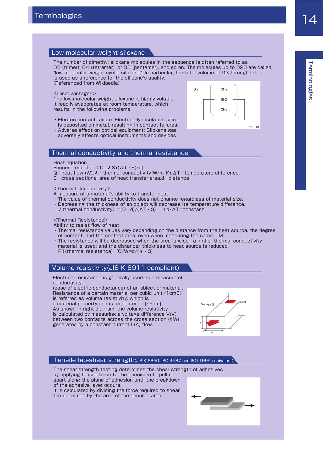
Low-molecular-weight siloxane
The number of dimethyl siloxane molecules in the sequence is often referred to as D3 (trimer), D4 (tetramer), or D5 (pentamer), and so on. The molecules up to D20 are called "low molecular weight cyclic siloxane". In particular, the total volume of D3 through D10 is used as a reference for the silicone's quality. (Referenced from Wikipedia)
<Disadvantages> The low-molecular-weight siloxane is highly volatile. It readily evaporates at room temperature, which results in the following problems. Dn :
CH3
Si-0
CH3
Terminologies
・ Electric contact failure: Electrically insulative silica is deposited on metal, resulting in contact failures.
・ Adverse effect on optical equipment: Siloxane gas adversely affects optical instruments and devices n n=3~10
Thermal conductivity and thermal resistance
Heat equation Fourier's equation:Q=λ×((ΔT ・ S)/d) Q:heat flow (W),λ:thermal conductivity(W/m ・ K),ΔT:temperature difference, S:cross sectional area of heat transfer area,d:distance
<Thermal Conductivity> A measure of a material's ability to transfer heat ・The value of thermal conductivity does not change regardless of material size. ・Decreasing the thickness of an object will decrease its temperature difference. λ(thermal conductivity)=(Q・d)/(ΔT・S) *d/ΔT=constant
<Thermal Resistance> Ability to resist flow of heat ・ Thermal resistance values vary depending on the distance from the heat source, the degree of contact, and the contact area, even when measuring the same TIM.
・ The resistance will be decreased when the area is wider; a higher thermal conductivity material is used; and the distance/ thickness to heat source is reduced. R1(thermal resistance):℃/W=d/(λ・ S)
Volume resistivity(JIS K 6911 compliant)
Electrical resistance is generally used as a measure of conductivity (ease of electric conductance) of an object or material. Resistance of a certain material per cubic unit (1cm3) is referred as volume resistivity, which is a material property and is measured in [Ω·cm]. As shown in right diagram, the volume resistivity is calculated by measuring a voltage difference V(V) between two contacts across the cross section (t·W) generated by a constant current I (A) flow. t Voltage V
L
Current I
W
Tensile lap-shear strength(JIS K 6850: ISO 4587 and ISO 1995 equivalent)
The shear strength testing determines the shear strength of adhesives by applying tensile force to the specimen to pull it apart along the plane of adhesion until the breakdown of the adhesive layer occurs. It is calculated by dividing the force required to shear the specimen by the area of the sheared area.
Global Network
Global Network
KITAGAWA INDUSTRIES CO., LTD. 695-1, Higashiorido, Mukui-cho, Inazawa City, Aichi Prefecture 492-8446, Japan Tel: 81-587-34-3561 Fax: 81-587-34-3109 https://www.kitagawa-ind.com/
KITAGAWA INDUSTRIES America, Inc. 2860 Zanker Road, Suite#102 San Jose, California 95134, U.S.A. Tel: 1-408-971-2055 Fax: 1-408-971-6033 https://www.kgs-ind.com/
KITAGAWA GmbH Birkenwaldstr.38, 63179 Obertshausen, Germany Tel: 49-6104-60009-0 Fax: 49-6104-60009-40 https://www.kitagawa.de/
KITAGAWA ELECTRONICS (SINGAPORE) PTE. LTD. 2 Bulim Lane 1, #03-11/12 Bulim Square, Singapore 648115 Tel: 65-6560-6511 Fax: 65-6560-6211 https://kitagawa-ind.com.sg/
KITAGAWA ELECTRONICS (THAILAND) CO., LTD. 999/100 Moo 15, Bangsaothong, Bangsaothong, Samutprakarn 10570, Thailand Tel: 66-2-182-5264 https://kitagawa-ind.co.th/
SHANGHAI KITAGAWA INDUSTRIES CO., LTD. 9F NO.7 Bldg No.77 3rd West Fu Te Road, China (Shanghai) Pilot Free Trade Zone, Shanghai 200131, China Tel: 86-21-5865-2766 Fax: 86-21-5064-4018
KITAGAWA TECHNOLOGY (SHENZHEN) CO., LTD. Room09-10, 11/F., Office Tower, Shun Hing Square DI Wang Commercial Center, 5002 Shen Nan Dong Road, Shenzhen City 518002, China Tel: 86-755-2396-3200 Fax: 86-755-2396-3490
KITAGAWA INDUSTRlES (H.K.) LIMITED Unit J, 15th Floor, Ever Gain Centre, 43-57 Wang Wo Tsai Street, Tsuen Wan, New Territory, Hong Kong Tel: 852-2612-1161 Fax: 852-2612-1686 https://kitagawa-ind.com.hk/
KITAGAWA INDUSTRIES (TAIWAN) CO., LTD. 7F, No.75, Hsin Tai Wu Rd., Sec.1, Hsi Chih Dist., New Taipei City, Taiwan, 221 Tel: 886-2-2698-8833 Fax: 886-2-2698-3355 https://kitagawa-ind.com.tw/
https://www.kitagawa-ind.com/
APR.2026 Printed No.20301009B 64